Main-Tie-Main Switchgear: What the Spec Asks You to Price

If you have quoted a double-ended lineup, you know how little the one-line diagram says about it. It shows two mains, one tie, three breaker symbols and a note that the tie is normally open.
Main-tie-main switchgear looks like the simplest drawing in the package. It is also the part of a low voltage quote where two manufacturers reading the same page most often price different things.
I spent two days with the documents that say what the drawing does not. They came in three kinds:
- I read the written standards of six universities that publish their rules for double-ended substations.
- I read a relay maker's application note for a three relay transfer scheme.
- I read a key interlock maker's guide.
The six owners agree on the three breakers. They disagree on almost everything those breakers are told to do.
This article is for the applications engineer or estimator who has to price that disagreement. It covers what a main-tie-main is, the five decisions the one-line does not show, and what each of the six owners requires.
It also covers where the cost hides in closed transition, key interlocks and the transfer scheme, and it ends with seven questions to settle before the number goes out.
It is the companion to our article on UL 891 vs UL 1558, which covers the enclosure and breakers the scheme sits in.
In brief
- A main-tie-main has two sources, two buses and a tie breaker between the buses that is normally open. Either source can carry both buses when the other is lost.
- The drawing shows three breakers. The price is in what tells them when to move: the transfer scheme, the interlocks, the control power and the testing.
- Six owners give six different answers. Yale wants automatic retransfer with closed transition and names the controller. Pennsylvania allows closed transition only by hand, under a synchronism check, and names a different controller.
- Closed transition ties the two sources together for a moment. A relay maker's own application note warns that the fault current available during that moment is doubled and can exceed what the breakers are rated to interrupt.
- Key interlocks and closed transition pull in opposite directions. Keys make it impossible to close all three breakers. Closed transition requires it, briefly.
- One owner requires a witnessed factory test of every automatic transfer scheme. That is days of someone's time, and it belongs in the quote.
What a main-tie-main is, and what double-ended switchgear means
What is a main-tie-main? It is two of everything, joined in the middle.
Two incoming sources, usually two transformers, each feed their own bus through a main breaker. A third breaker, the tie, joins the two buses and is normally open, so in normal running each source carries half the building.
If one source is lost, three things happen in order:
- Its main opens.
- The tie closes.
- The remaining source carries both buses.
Double-ended and secondary selective
The same arrangement goes by other names. Double-ended switchgear and double-ended substation mean the lineup has a source at each end.
Engineers who design them also call the arrangement secondary selective, because the choice between sources is made on the low voltage side.
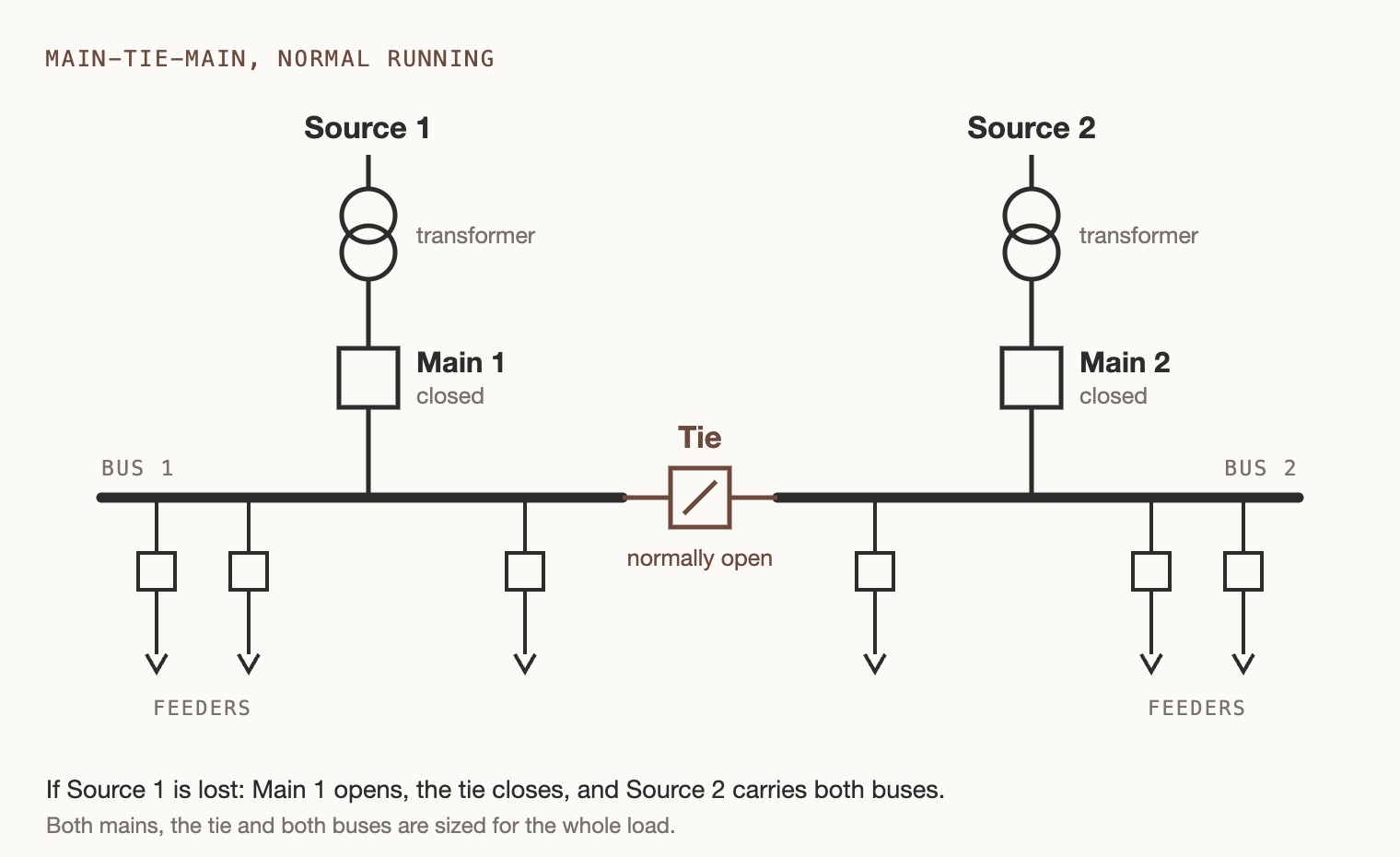
Three things follow from that picture, and all three reach the price.
Each source has to carry everything
The University of Michigan's design guideline puts numbers on it. A transformer's self-cooled rating is the load it can carry without its cooling fans running. Michigan's guideline sizes that rating like this:
- A single-ended substation is sized so the transformer's self-cooled rating is about 150 percent of the projected peak demand.
- In a double-ended substation, each transformer's self-cooled rating is about 115 percent of the peak demand of the whole substation, both ends together.
The University of Pennsylvania's standard reaches the same place by a different route. With one end out, the surviving transformer carries the whole diversified load at 70 percent or less of its fan cooled rating.
For the manufacturer the consequence is simple. Both mains, the tie and both buses are sized for the whole load, not for half of it.
The tie is a full size breaker
Michigan requires the tie breaker to be identical to the mains and able to change places with either one. Northwestern University requires mains and ties on a frame of at least 3,200 amps.
Nobody should price the tie as a feeder.
It is bought for buildings that cannot go dark
Dartmouth College's guidelines say double-ended substations are preferred for critical facilities only. They give data centers, chiller and heating plants, and research buildings as examples.
That tells you who is on the other side of the quote. It is someone who is paying for continuity and will read the transfer scheme closely.
Main-tie-main switchgear: five decisions the one-line does not show
A one-line diagram for main-tie-main switchgear shows what is connected to what. It does not show what the breakers do when a source fails, when it comes back, or when an electrician wants to take a transformer out for maintenance on a Tuesday.
Those are five separate decisions, and the specification may make all of them, some of them, or none.
| Decision | The choices | What it adds to the quote |
|---|---|---|
| 1. Who moves the breakers | A person. A person, with electrical safeguards. A controller, automatically. | Electrically operated breakers, voltage sensing, a controller, selector switches |
| 2. Open or closed transition | Break before make. Make before break. One for the transfer and the other for the return. | A synchronism check, timing logic, and a question about the fault rating |
| 3. How the sources are kept apart | Key interlocks. Electrical interlocks. A time limit on how long they may be joined. | Locks and keys, or interlock wiring and relays, or both |
| 4. What does the thinking | Protective relays. A programmable controller. A named make of either. | Named devices, settings, programming hours, test hours |
| 5. One tie or two | Main-tie-main. Main-tie-tie-main. | A fourth breaker and its cell, more bus, more interlocking |
The rest of this article takes those five in turn, after a look at how differently six owners answer them.
What six owners require
These six universities publish their electrical standards, and each one has something specific to say about the tie.
The table compresses each document into one row. The paragraph numbers are each document's own.
| Owner | Transfer | Transition | Keeping the sources apart | Controller |
|---|---|---|---|---|
| Pennsylvania, 26 10 00, sections 4.0, 5.0 and 9.0 | Automatic throwover on the primary switchgear unless the university permits otherwise. The secondary is manual when the primary does the transferring. | Closed transition only in manual mode, supervised by a synchronism check | Key interlocks or another non-defeatable means where a manual scheme has no electrical interlocks | A named make of relay and controller. The university supplies wiring diagrams and settings files. |
| Yale, Subdivision 16300, unit substations | Automatic transfer and automatic retransfer | Retransfer with closed transition. No delay on transfer, ten seconds on retransfer. | The two sources electrically interlocked | A named make of programmable controller, no substitutes, on its own uninterruptible supply |
| Michigan, Design Guideline 26 11 00 | Automatic or manual, by selector switch | Closed transition whenever an energized bus is transferred or retransferred | A key interlock on the tie if there are no automatic controls | Not named |
| Dartmouth, 26 24 13, paragraph 1.2.E | Enhanced manual controls with automatic safeguards as the baseline. The manufacturer presents the scheme during design. | Closed transition where feasible | Safeguards against closing into a fault | Automated controls, described as now standard |
| Houston, 26 24 14, paragraphs 2.3.H and 2.3.I | A manually operated throw-over as drawn, with a residual automatic transfer in the optional text | Momentary paralleling in the main-tie-tie-main option | Kirk key interlocks between main, tie and main | Not named |
| Northwestern, 26 2300, paragraphs 2.3, 2.4.J and 2.5 | An electrically interlocked arrangement as an option | Not stated | Kirk key interlocks, with two spare sets of keys signed for | Interlocking relays on the control power |
Yale and Pennsylvania reach opposite answers
Look at the first two rows together. Yale and Pennsylvania are both campuses with their own medium voltage distribution, and they have reached opposite conclusions about the same question.
- Yale wants the lineup to go back to normal by itself, without an outage, ten seconds after the source has been stable.
- Pennsylvania does not let the equipment parallel two sources unless a person has put it in manual and a relay has confirmed the sources are in step. To parallel two sources means to join them together through the lineup.
Each one names a different controller
Each also names its controller, and they name different kinds of device from different makers. Yale names a programmable controller. Pennsylvania names protective relays and an automation controller.
If your standard scheme is built around a third make, both documents ask you to rebuild it around theirs.
Dartmouth asks you to present the scheme
Dartmouth goes the other way and leaves much more to the manufacturer. It asks the manufacturer to present the transfer controls and discuss them during design.
That is an invitation, and also a cost. Someone on your side prepares that presentation before there is an order.
Open or closed transition, and the fault current that comes with it
There are two ways to move a bus from one source to the other:
- An open transition is break before make. The main on the failed side opens, and only then does the tie close. For a moment the affected bus is dead.
- A closed transition is make before break. The tie closes while both mains are still closed, and then one main opens. Nothing goes dark, but for a moment the two sources are joined through the lineup.
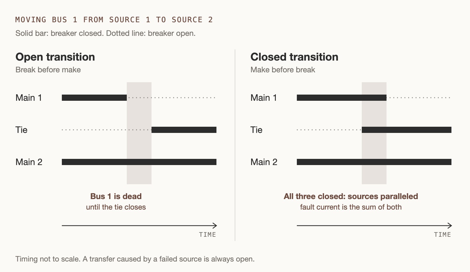
Two facts help in reading a specification on this point.
A transfer after a source fails is open by nature
First, a transfer caused by a failed source is open by nature. The source is gone, so there is nothing to parallel with.
Closed transition applies to the planned moves. There are two of them:
- One is transferring a healthy bus so a transformer can be serviced.
- The other is the return to normal after a failed source comes back.
That is why Yale's list asks for closed transition on the retransfer. It is also why the relay maker's application note I read, General Electric's GET-8558, lists automatic transfer as open transition and automatic retransfer as an optional closed transition.
Why the open transfer waits
Second, the open transfer is not instant, and the reason is motors. Motors on a bus that has just lost its source keep turning and keep generating voltage for a short time.
Closing the tie onto that voltage while it is out of step with the new source is hard on the motors and on the gear.
The scheme in the GE note is called a residual bus scheme for that reason. It waits for the leftover voltage to die down, to a quarter of normal by default, before it closes the tie.
If a specification says residual transfer, that waiting logic and the voltage sensing behind it are part of what you are quoting.
The fault current doubles while the sources are joined
Now comes the part that is easy to miss. The same application note describes what happens while all three breakers are closed.
Two transformers are paralleled, and if a fault occurs on a feeder in that moment, the short-circuit current is doubled.
The note says plainly that the increased current may exceed the interrupting rating of the breakers. The interrupting rating is the largest fault current a breaker can safely cut off. The note adds that the paralleling time should therefore be set as short as possible.
What closed transition adds to the quote
So a closed transition requirement asks three things of a quote, and a one-line shows none of them:
- The first is a synchronism check. That is a relay function that confirms the two sources are in step before they are joined. Pennsylvania requires every closed transition to be supervised by the sync check function of its named relay. Yale asks for a sync check relay if it is required by the manufacturer, which hands the decision to you.
- The second is logic to end the parallel. Pennsylvania calls it trip select. After the parallel, the scheme automatically trips the breaker the operator chose. Something has to time that and act on it.
- The third is an answer on the fault rating. Either the lineup and its feeder breakers are rated for the fault current of both sources together, or the time in parallel is limited and somebody states the limit. None of the six owner documents says which.
Send the fault rating question before pricing, because the two answers are different lineups.
Three owners take three positions
- Michigan requires closed transition whenever an energized bus is transferred or retransferred.
- Dartmouth wants it where feasible.
- Pennsylvania allows it only in manual.
That makes three owners with three positions. A default scheme that satisfies one of them will be an exception at the other two.
Main-tie-main Kirk key interlocks: two keys for three breakers
A key interlock is a lock on a breaker that traps a key. The interlock maker's own guide describes the principle with a larger example, four mains and three ties, and the rule is the same at any size.
How the keys move
The rule works like this:
- Each main breaker holds its key while the breaker is closed.
- The key comes out only when that main has been opened and locked open.
- The tie is normally locked open and holds no key of its own.
- To close the tie, an operator must bring it a key, and the only way to get one is to lock a main open first.
What that means for one tie and two mains
Apply that to one tie and two mains and you have two keys for three locks. Any two of the three breakers can be closed, but all three never can.
The guide makes the point that this is stronger than a padlock and a tag. The unsafe operation is not forbidden, it is impossible, because the key that would allow it is somewhere else.
What four of the six owners require
Four of the six owners write key interlocks into their standards, each with a condition attached:
- Michigan wants a key interlock on double-ended substations that are designed without automatic transfer controls, so the tie cannot be operated unless one main is open.
- Houston wants Kirk key interlocks between main, tie and main on a manually operated throw-over scheme, as shown on the one-line.
- Pennsylvania allows manual-only schemes only with permission, and then requires key interlocks or another feature that cannot be defeated.
- Northwestern asks for key interlocks as shown on the drawings, and for mountings and hardware where future interlocks are indicated. In its list of maintenance materials, it also asks for two spare sets of keys that the university's chief electrician receives and signs for.
Why the spare keys need a signature
That last requirement is worth a second look. A key interlock works because there is exactly one key, and a spare key in a desk drawer defeats it.
Northwestern's answer is custody. The spares exist, and one named person signs for them.
If you quote that section, the spare keys are a line item and the handover is a step in your closeout.
Keys and closed transition pull against each other
The other thing to notice is the conflict built into the hardware. Key interlocks make it impossible to close all three breakers. Closed transition requires all three to be closed for a moment.
A specification that asks for both has to say how.
Houston's master text shows the tension on the page. The sentence that requires key interlocks is followed by bracketed optional text about a main-tie-tie-main that allows momentary paralleling.
The bracket is there for a project editor to accept or delete.
If the project section you receive kept both, ask which one governs before you price the locks.
Main-tie-main transfer scheme: what is inside the word automatic
A specification can spend one word on this, and the word is automatic. The documents show how much is inside it.
What the GE note lists
The table of contents of the GE application note reads like a list of things someone has to design, wire, set and test.
It covers a transfer mode selector switch, synchronism check, lockout functions, breaker operations in the test position, live source seeking, and what to do when both sources are lost at once. Its scheme uses three relays, one for each breaker.
A bill of material for the transfer scheme
Putting the six owner documents beside that note gives a fair bill of material for a main-tie-main transfer scheme.
Not every job needs every line. Every line appears in at least one of the documents.
| Part of the scheme | What the documents ask for | Where |
|---|---|---|
| Breakers that can be closed by a signal | Mains and ties electrically operated, each with its own charging motor | Michigan. Northwestern 2.5 for main-tie-main. Yale. |
| Knowing a source is bad | Undervoltage sensing on both sources. Phase loss and phase sequence sensing. Set points written in the standard. | Yale, automatic throwover features 6 to 8 |
| Knowing two sources are in step | A synchronism check for every closed transition | Pennsylvania 5.0.E. Yale feature 16. |
| The controller | Protective relays, an automation controller or a programmable controller, by a named maker | Pennsylvania 5.0.G. Yale feature 12. |
| Control power that survives losing a source | Two control power transformers, each on the line side of its own main, with transfer relays. Or an uninterruptible supply for the controller. | Northwestern 2.4.J.2. Yale. Dartmouth 1.2.E.2. |
| What the operator touches | An automatic or manual selector. A test switch that simulates losing either source. A button that inhibits manual operation. Lockout with a light. | Pennsylvania 5.0.C. Michigan. Yale features 3, 14 and 15. |
| Modes to program | Live source seeking. A mode for when automatic cannot be entered. Trip selection after a parallel. Full automatic operation with a breaker in the test position. | Pennsylvania 5.0.D to 5.0.F. Yale feature 13. |
| Timing that depends on others | Delays coordinated so the medium voltage scheme reacts before the low voltage one | Pennsylvania 5.0.A and 5.0.B |
| Proof that it works | Witness testing at the factory for all equipment with automatic transfer schemes | Pennsylvania 5.0.J |
Three lines in that table deserve a comment.
Control power
A transfer scheme has to operate at the exact moment a source has failed. If the control power came from that source, the scheme is dead when it is needed.
That is why Northwestern asks for two control power transformers in separate compartments with relays to switch between them. It is also why Yale and Dartmouth want an uninterruptible supply.
Control power is a small part of the price and the first thing that fails a factory test.
Settings and responsibility
Pennsylvania supplies standard wiring diagrams and settings files for its named devices, which sounds like free engineering.
Paragraph 5.0.H takes most of it back. Using the university's material does not relieve the design firm or the manufacturer of responsibility for a properly operating system, and both are expected to be well versed in programming those devices.
The files save typing. The hours to understand, adapt and prove the scheme are still yours.
The witness test
Pennsylvania requires a witnessed factory test for every automatic scheme.
The GE note adds a caution of its own for that test. The breakers should never be closed with their mechanical close buttons during a factory acceptance test, because that bypasses the relay logic the test is meant to prove.
A witnessed test means a test procedure, a simulated loss of each source, the owner's people in your plant, and time on the floor.
We wrote about how widely those requirements vary between owners in the guide on how to quote switchgear.
Main-tie-main vs main-tie-tie-main
Some lineups have two tie breakers in series, one after the other, between the buses. Two of the six owners mention the arrangement:
- Michigan tells its designers to discuss it with the university's primary system engineer project by project, and to modify the specification if it is approved.
- Houston's master text carries it as an option and gives the reason in a bracket. With two ties, a tie can be tested without a total outage.
Why two ties let you work on one
That reason is physical. A single tie breaker sits in a cell that is connected to both buses. To work safely on that cell, both buses have to be dead, which means the whole lineup is out.
With two ties, each one can be isolated from one side by the other, so the lineup can stay half alive while a tie is serviced.
What the second tie adds to the quote
For the quote, main-tie-main vs main-tie-tie-main is the difference of a fourth breaker, and under Michigan's rule that breaker is identical to the mains.
It also adds a fourth cell, the bus between the two ties, another set of interlocks, and a transfer scheme that has to know about four breakers instead of three.
If the one-line shows one tie and the text mentions two, or the other way round, treat it as a count question and take the count from the drawing.
What the tie does to the ratings and the layout
Beyond the scheme, the same documents attach a handful of physical requirements to the main and tie sections. They are easy to price once you know to look.
Inside the main and tie sections
- Northwestern's switchgear section asks for the barriers between main and tie breaker compartments to be extended to the rear of the section. It also asks for the line bus to be isolated from the load bus at each main and tie.
- The same section lists a four-wire, double-ended substation as its own arrangement for ground fault sensing, separate from an ordinary four-wire system. It needs its own sensor arrangement, so check that your standard scheme covers it.
- Pennsylvania asks for surge protective devices on both sides of the tie in a double-ended lineup. That is two devices where a single-ended lineup has one.
For maintenance and operation
- Houston asks for infrared scanning windows in the rear covers of the main sections, including the main-tie-main sections.
- Dartmouth wants the transfer controls to let electricians operate the lineup remotely. Houston wants remote racking and operation of the breakers. Racking means moving a breaker in or out of its connected position. A remote operator station is hardware and wiring.
- Michigan requires the instantaneous trip on mains and ties to be defeatable, which means it can be switched off. It also requires the main and tie trip units to include a way of reducing arc flash energy during maintenance.
Which enclosure the scheme sits in
The enclosure these sit in matters too. A scheme with relays, a controller and compartmented mains and ties usually means switchgear, not a switchboard.
The companion article linked at the top explains how to tell which one a specification is describing.
Seven questions to settle before you price a main-tie-main lineup
These come straight from the gaps between the six documents. If the project section answers all seven, price it.
If it does not, each unanswered one is a clarification in the quote or a question to the engineer.
- Is the transfer manual, automatic, or both with a selector? And is the baseline what Dartmouth calls enhanced manual, or a full automatic scheme?
- Is any transfer closed transition? If so, which direction does it go in, and does it happen in automatic or only in manual?
- During a closed transition, what is the fault rating? Is the lineup rated for both sources together, or is the time in parallel limited, and who states the limit?
- What keeps the sources apart? It could be keys, electrical interlocks, or both. If keys and closed transition both appear, which governs?
- Is the controller named? Who supplies the settings, who programs it, and who is responsible when it does not work?
- Where does control power come from when one source is dead?
- Who witnesses the test, and where? And does another scheme upstream set the timing of yours?
Where the answers go
Each of those is a row in a compliance matrix, which is a table with one row per requirement and your answer beside it.
Our specification compliance matrix has a row for transfer schemes in its switchgear starter set, and a blank sheet for the rest.
The answers you write there become the clarifications page. That page is where a buyer comparing two prices finds out that the two manufacturers priced different schemes.
For every question the project section leaves open, write a clarification into the quote or send the question to the engineer.
A real case from a Texas water district
A real case shows what happens when they are not settled. One of the public submittal records we read for an earlier article was a 4,160 volt main-tie-main lineup for a Texas water district.
Two reviewers from the same engineering firm reviewed the same package. One approved it as noted and the other rejected it.
That record is in what engineers actually reject.
Why a quoting company wrote this
Mavlon builds software that reads a customer's specification and drawings when the request for quote arrives. It does three things:
- It lists every requirement that changes the price.
- It ties each one to its page.
- It flags the ones that disagree, such as a section that requires key interlocks and closed transition in the same paragraph.
Your estimator decides what to do about each flag, and the quote is drafted in your own pricing rules.
A main-tie-main section is a good test of any reading tool, because the expensive sentences are short and scattered. If your team quotes double-ended lineups from specifications, we would be glad to read one with you.
Sources
- University of Pennsylvania, Design Standards 26 10 00, Power Distribution System and Equipment, revision July 2019, sections 4.0, 5.0 and 9.0.
- Yale University, Design Standards, Subdivision 16300, Transmission and Distribution, revision 3, April 2009, secondary unit substations.
- University of Michigan, Design Guideline 26 11 00, Unit Substations, February 2023.
- Dartmouth College, Design and Construction Guidelines 26 24 13, January 2023, paragraph 1.2.E.
- University of Houston, Master Specification 26 24 14, Low Voltage Switchgear, August 2020, paragraphs 2.3.H and 2.3.I.
- Northwestern University, Section 26 2300, Low-Voltage Switchgear, issued 29 March 2017.
- GE, Application Note GET-8558, Residual Bus Main-Tie-Main Automatic Transfer Scheme Using Three GE 850 Relays, revision 00, 18 October 2013.
- Kirk Key Interlock Company, Examples of Key Interlock Systems, white paper.
Found a mistake? Write to atishay@mavlon.co and we will fix it.
Talk to us about your specifications
If your team quotes double-ended lineups from customer specifications, bring one. We will read it with you and show every sentence about the transfer scheme, the interlocks and the tie, tied to its page.
Or read what Mavlon does for switchgear and switchboard builders, on one page: AI quoting for switchgear and switchboard manufacturers.
Book a demo