Data Center Single Line Diagram: How to Read It for a Quote

I spent a day this week with one drawing. It is sheet A06 of a public project in Bogotá, Colombia, and it is the data center single line diagram for a new geoscience research building.
The sheet is a single page. It holds 39 pieces of equipment, two generators, four large UPS units and dozens of breaker ratings, and every label on it is in Spanish.
If your company makes switchgear, switchboards, transformers, generator sets or UPS systems, a sheet like this is where most of your quote comes from. It is also the page where two people on the same team can read two different scopes.
This guide reads that sheet from the top to the bottom, in the order an estimator or an applications engineer would read it. For each block I explain what the drawing tells you, what it leaves out, and what you should ask before a price goes out.
I also put the sheet next to the building's general diagram and the written specification. The three documents do not describe the same transformer, and they do not agree on who supplies the generators.
If you want the same kind of reading for a medium-voltage switchgear lineup, our page about AI to read electrical drawings goes through two public switchgear drawings panel by panel.
In brief
- A single line diagram draws a three-phase power system with one line for each circuit. In the United States the same drawing is called a one-line diagram.
- You read it from the source down. On this sheet the power comes in at 11.4 kV, passes four medium-voltage cells, and a 700 kVA dry transformer steps it down to 480 V.
- Below the transformer, everything is doubled. There is a main board A and a main board B, and each one has its own automatic transfer, its own pair of 120 kVA UPS units and its own cooling board.
- The small numbers beside each symbol are the quote. A label such as "3 X 1000 A", "Ir=0.95XIn" or "Ikmax=25KA" decides which breaker and which bus you price.
- The drawing leaves out lengths, tests and construction details. Twelve bus duct runs on this sheet have a current rating and no length.
- Two sheets draw the data center transformer in two different ways. Sheet A06 shows 700 kVA at 480/277 V, and the building's general diagram shows 800 kVA at 208 V.
- The specification says the generators and the UPS units may not be part of the contract, and in the same sentence it says they must be in the offer.
What a data center single line diagram shows
A power system in a building has three phase wires, often a neutral, and a ground. A drawing that showed every wire would be impossible to read.
A single line diagram solves this by drawing one line for each circuit. Each line stands for all the wires of that circuit, and each symbol on the line stands for one piece of equipment.
The name changes with the country. Engineers in the United States say one-line diagram. Engineers in most other countries say single line diagram or SLD, and the title block of this Colombian sheet says "Diagrama unifilar". All three names mean the same drawing.
What the drawing is good at
It answers four questions quickly:
- It shows where the power comes from. On this sheet that means the utility, two generators and the UPS batteries.
- It shows the order of the equipment, so you can see what feeds what.
- It shows the main ratings, such as the voltage, the current of each breaker and the fault current each board must withstand.
- It shows how much of the system is doubled, which tells you how the site keeps running when one part fails.
What the drawing does not show
A single line diagram is not a layout. It does not tell you how far apart two boards are, how long a cable or a bus duct is, or which room a board stands in.
It also says very little about how the equipment is built. The enclosure, the paint, the wiring of the controls, the factory tests and the spare parts are normally in the specification.
This is why a quote needs both documents. The drawing tells you how many items there are and how big they are. The specification tells you how each item must be made and tested.
Why the data center version is harder to read
An office building usually has one source and one path. A data center has several sources and at least two paths, because the servers must stay on while a part of the system is switched off for repair.
Three short terms describe how much spare equipment a site has, and you will see them on almost every data center drawing:
- N is the amount of equipment the load needs. If the servers need one 120 kVA UPS, then N is one UPS.
- N+1 means you have one extra unit beyond what the load needs. On this sheet the label "1+1" on a UPS board says exactly this: one UPS carries the load, and a second one stands beside it.
- 2N means the site has two complete and separate paths, and each path can carry the whole load. Drawings usually call the two paths A and B.
The sheet in this guide combines the last two ideas. It has a side A and a side B, and each side has a 1+1 pair of UPS units.
A data center single line diagram example from a public project
The project is the Centro de Excelencia en Geociencias, a research building of the Servicio Geológico Colombiano, which is Colombia's national geological survey. The survey published the design files of the building on its own website, and the links are at the end of this guide.
I used three of those files:
| Document | What it is | What it holds for a quote |
|---|---|---|
| Sheet A06, "Diagrama unifilar" | The one-page diagram of the data center, dated August 2017 | Every board, breaker rating, UPS unit and generator, and a numbered list of 39 pieces of equipment |
| Sheet U-B1-1 | The general diagram of the whole building, version 4, dated 30 May 2018 | The building's medium-voltage room and its transformers, including the one marked for the data center |
| Specification 09, electrical installations | The written electrical specification of the building, 67 pages | How the cells, transformers, bus ducts, UPS units and generators must be built, tested and paid for |
All three are in Spanish. I read them by hand, and where I give the specification in English, the translation is my own.
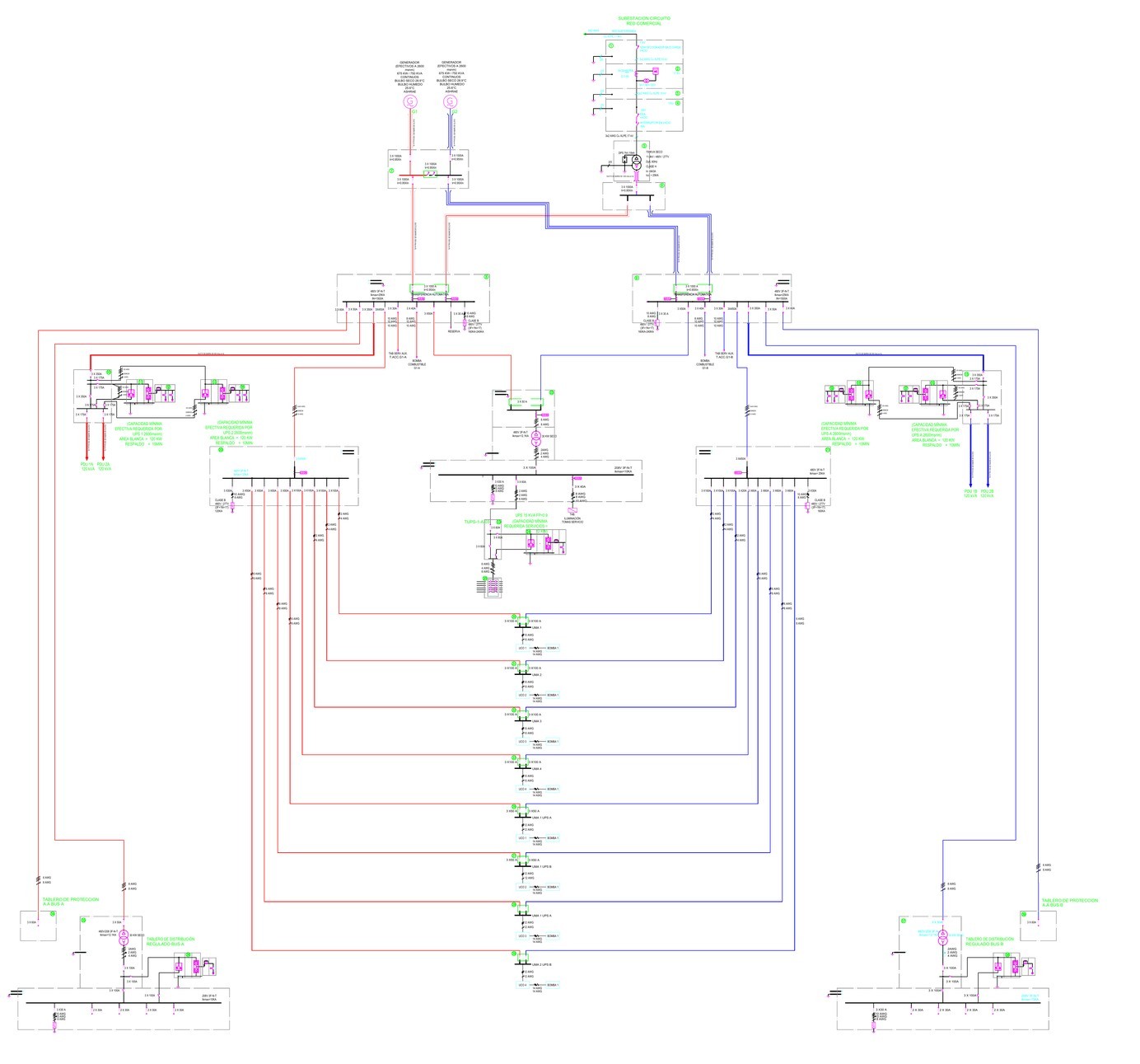
Start with the legend and the colours
Before you read any rating, find the legend. On this sheet it explains each symbol in words, such as the breaker, the load-break switch, the current transformer and the surge protection device.
The legend also explains the colours. A red line is a feeder of bus A, and a blue line is a feeder of bus B. Once you know this, the page becomes much easier to follow, because you can see right away which side a board belongs to.
The green circles with numbers are item numbers. Each one points to a row in the equipment list at the side of the sheet, and that list is the closest thing the drawing has to a bill of materials.
Print the equipment list and tick each row as you find its number on the drawing. If something is in the list and not on the drawing, or on the drawing and not in the list, it becomes your first question for the customer.
The top of the sheet: the utility service and four medium-voltage cells
Power enters at the top right, under the words "SUBESTACION CIRCUITO RED COMERCIAL", which means the substation on the utility circuit. A note beside the line says "RED SUBTERRANEA", so the supply arrives by an underground cable.
The cable is marked as three copper conductors with XLPE insulation at 11.4 kV. That is the first number to write down: the service voltage on the diagram is 11.4 kV.
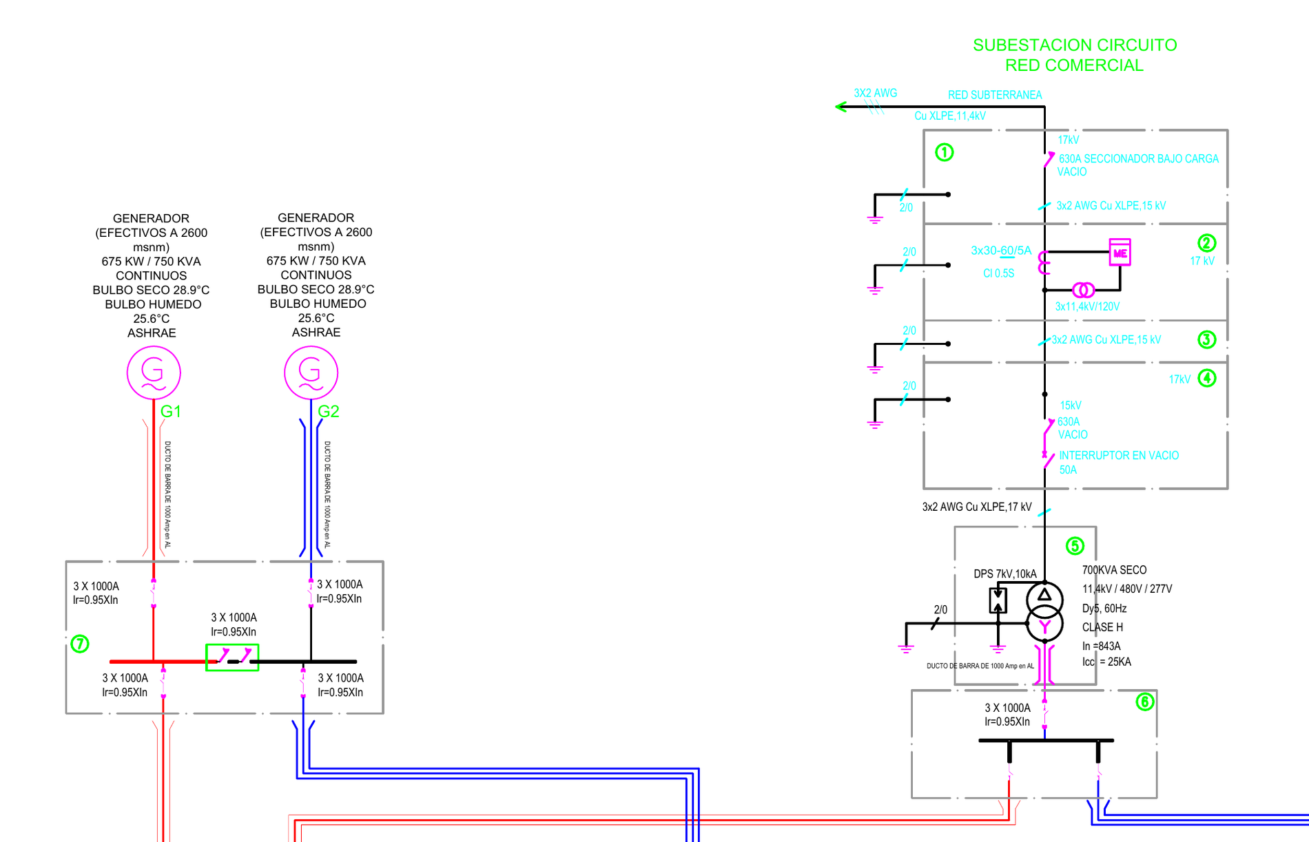
Below the cable there are four boxes with dashed outlines, numbered 1 to 4. Each box is one medium-voltage cell. A cell is a metal cabinet that holds one function of the switchgear.
Cell 1: the load-break switch
The first cell holds a switch marked 17 kV and 630 A, with the words "SECCIONADOR BAJO CARGA". A load-break switch can open and close the circuit while normal current is flowing. It cannot clear a short circuit by itself.
The rating of 17 kV is higher than the service voltage of 11.4 kV. This is normal, because switchgear is built in standard voltage classes and the designer picks a class above the system voltage.
Cell 2: the metering cell
The second cell measures the energy the data center uses. The equipment list calls it a metering cell "de 3 Elementos", which means it measures all three phases.
Two sets of instrument transformers feed the meter:
- The current transformers are marked "3x30-60/5A" with class 0.5S. They turn a line current of 30 or 60 A into 5 A for the meter, and the two numbers mean the ratio can be changed.
- The voltage transformers are marked "3x11,4kV/120V". They turn the line voltage into 120 V for the meter.
Class 0.5S is an accuracy class used for billing meters. If your quote includes this cell, the class matters for the price, because instrument transformers of billing accuracy are a different part from ordinary ones.
Cell 3: the riser cell
The third cell is almost empty on the drawing, and the list calls it a "Celda de Remonte", which is a riser cell. It holds no switching device. Its job is to carry the conductors from one cell across to the next.
A riser cell is easy to miss because it has no symbol inside it. It is still a cabinet with conductors and an earth connection, and it has a price.
Cell 4: the transformer protection cell
The fourth cell protects the transformer. It shows a switch marked 15 kV and 630 A, and below it a breaker with the words "INTERRUPTOR EN VACIO" and 50 A, which means a vacuum circuit breaker.
A medium-voltage breaker is normally built for several hundred amperes, so 50 A is most likely a protection setting. The full-load current of a 700 kVA transformer at 11.4 kV is about 35 A, which fits. The drawing does not say which it is.
A breaker also needs a relay to tell it when to open. The drawing shows no relay and no current transformers in this cell, so the protection scheme is one of the things you have to ask about.
What the specification adds about the cells
The drawing says "VACIO", which means vacuum, beside the switching devices. The specification describes something else. Its section on the cells has the heading "CELDAS DE MEDIA TENSION SF6", and it asks for cells that use SF6 gas to insulate and to interrupt, with SF6 circuit breakers.
"Las celdas en SF6 deben ser compuestas por unidades modulares bajo envolventes metálicas"
Specification 09, section 14.5.1, printed page 41In English, the sentence says that the SF6 cells must be made of modular units in metal enclosures.
Vacuum and SF6 are two different ways to put out the arc when a breaker opens. A manufacturer usually offers one or the other in a given product line, so this difference can decide which product you are allowed to offer.
Ask three things about the cells before you price them:
- Ask whether the switching devices are vacuum as drawn or SF6 as specified.
- Ask which relay and which current transformers protect the transformer.
- Ask whether the four cells on sheet A06 are extra cells for the data center or the same cells drawn a second time, because the building's general diagram has a medium-voltage room of its own.
The transformer block: six lines of text that set the price
Item 5 is the transformer. The symbol is two circles, one with a triangle inside it and one with a Y, and beside it there are six short lines of text. Each line changes what you quote.
| Label on the drawing | What it means | Why it matters for the quote |
|---|---|---|
| 700 kVA seco | A dry-type transformer of 700 kVA, cooled by air and not by oil | It sets the size and the type of the unit |
| 11,4 kV / 480 V / 277 V | The primary is 11.4 kV. The secondary gives 480 V between phases and 277 V from a phase to the neutral | It sets the windings, and it means the neutral must be brought out |
| Dy5, 60 Hz | The primary winding is connected in delta and the secondary in star, with a fixed phase shift between them | A unit with a different connection group cannot be swapped in later |
| Clase H | The insulation is class H, which is made for a higher working temperature than class F | It decides the insulation materials and the construction |
| In = 843 A | The rated current on the 480 V side | It sizes the bus duct and the main breaker below |
| Icc = 25 kA | The short-circuit current on the 480 V side | It sets the short-circuit rating of the boards below |
You can check one of these numbers yourself. A 700 kVA transformer at 480 V delivers 700,000 divided by 480 and then by 1.732, which is about 842 A. The drawing says 843 A, so the label agrees with itself.
The small box beside the transformer marked "DPS 7kV,10kA" is a surge arrester on the primary side. DPS is the Spanish abbreviation for a surge protection device.
What the equipment list says about the same transformer
Now look at row 5 of the equipment list. It reads "Celda de Transformador de 700 kVA Seco k13 13200 / 480 / 277 VAC".
Two things in that row are not on the diagram:
- K13 is a K-factor. A K-rated transformer is built to carry the extra heating caused by the distorted current that computer power supplies draw. It is a heavier unit than a standard one, and it costs more.
- The primary voltage in the list is 13,200 V. The diagram on the same sheet says 11.4 kV.
So one sheet gives two primary voltages for one transformer. A transformer wound for the higher voltage and connected to the lower one would deliver well under 480 V, so you cannot leave this to a guess.
The specification points to the answer, because it describes the service as "11400 voltios, 60 ciclos" on printed page 4. The customer still has to correct the equipment list, because the list is what a buyer copies into a purchase order.
What the specification adds about the transformer
The specification spends several pages on the transformers. Five of its requirements change the price, and none of them is on the drawing:
- It asks for a dry transformer with windings "encapsulados en aislamiento sólido de resina epoxi", which means cast in solid epoxy resin, to the standard IEC 60076-11.
- It asks for high-voltage coils wound in aluminium.
- It asks for a steel enclosure with a protection degree of at least IP-21, and for three temperature sensors in the low-voltage coils.
- It asks for insulation of "clase F o superior", which means class F or higher. The drawing says class H, which is higher than F, so the two agree. The maker still has to confirm that one unit can be cast in resin, be class H and carry the K13 rating at the same time.
- It lists routine tests on every unit, including a partial discharge test, and three type tests: temperature rise, noise level and short circuit.
For the type tests, the maker must either show reports of tests on units of equal or greater power, or do what this line asks:
"presentar separadamente costos para realización de los ensayos tipo"
Specification 09, transformer tests, printed page 44In English, the maker must present the costs of carrying out the type tests separately. A short-circuit type test on a transformer is expensive, and it is the kind of line that is missing from a quote when you only read the drawing.
The generators and the synchronizing board
At the top left of the sheet there are two circles marked G1 and G2. These are the emergency generators.
The text above each one says "675 KW / 750 KVA" and "EFECTIVOS A 2600 msnm". The abbreviation msnm means metres above sea level, so each generator must deliver 675 kW continuously at 2,600 metres, which is the altitude of Bogotá.
Why the altitude is written on the drawing
An engine makes less power in thin air. A generator set that gives 750 kVA at sea level gives less than that at 2,600 metres, and how much less depends on the engine.
The drawing asks for the power after this loss, not before it. A generator packager therefore has to pick a larger set and prove the reduced output with the engine maker's data. The same note gives the design air temperatures, which are a dry bulb of 28.9 °C and a wet bulb of 25.6 °C.
We wrote about this step in more detail in our guide to data center generator sizing.
The synchronizing board, item 7
Each generator connects by a 1000 A aluminium bus duct to item 7, which the list calls "Tablero de Sincronismo de Generadores 1 y 2". That is the synchronizing board of the two generators.
The board has five switching positions, and the four breakers and the tie are all marked "3 X 1000A":
- There is one incoming breaker for generator 1 and one for generator 2.
- There is a tie between the two halves of the bus, drawn inside a green box.
- There are two outgoing breakers. One is on a red line that goes to main board A, and one is on a blue line that goes to main board B.
With the tie open, generator 1 feeds side A and generator 2 feeds side B. With the tie closed, both generators share one bus. Two generators can only share a bus after their voltage, frequency and phase have been matched, and that matching is called synchronizing.
The size also checks out. A 750 kVA generator at 480 V has a full-load current of about 902 A, so a 1000 A breaker fits.
What "Ir = 0.95 X In" means
Every large breaker on this sheet carries the note "Ir=0.95XIn". In is the rated current of the breaker, which here is 1000 A. Ir is the current at which its long-time protection starts to act.
So each of these breakers is to be set at 950 A. That tells you the breaker needs an adjustable trip unit, which on a breaker of this size normally means an electronic one, and that is a price difference on every one of these positions.
What the drawing leaves out about the board
The single line shows the breakers. It does not show the parts that make two generators work together: the synchronizer, the load-sharing controls, the protection relays and the logic that opens and closes the tie.
The specification does not fill this gap, and one sentence in it matters a great deal to the board maker. The section on the emergency plant says what the estimated price of the generators leaves out:
"No incluye los alimentadores, no incluye sincronismo"
Specification 09, section 14.10.2, printed page 56In English, it does not include the feeders and it does not include synchronizing.
If the generator price leaves the synchronizing out, the synchronizing controls have to be in someone else's price. The natural place is the board, and a board maker who prices item 7 as five devices in a cabinet will be far too low.
Our guide to paralleling switchgear explains what those controls are and how specifications describe them.
When a drawing shows two or more generators on one bus, look for the word that names the controls: synchronizing, paralleling or load sharing. If the specification gives it to nobody, write in your offer whether your board includes it, and price it as its own line.
Where the sheet splits into side A and side B
Below the transformer, item 6 is the "Tablero de Distribución General para Ramas A y B", which is the general distribution board for branches A and B. It has one main breaker marked "3 X 1000A" and two outgoing feeders. The red one goes to side A and the blue one goes to side B.
From this point down, the drawing is nearly symmetrical. Whatever you find on the left in red, you will find again on the right in blue.
The main boards, items 8 and 9
The two main boards are called TGBT A and TGBT B. TGBT is short for tablero general de baja tensión, which means the main low-voltage board, and it does the job that a main switchboard does on a drawing from the United States.
Each main board receives two feeders. One comes from the transformer through item 6, and one comes from the generators through item 7. Between them the drawing writes "TRANSFERENCIA AUTOMATICA".
So each side has its own automatic transfer between the utility and the generators. If the utility fails, side A moves to the generators by itself, and so does side B.
The bus of each board carries three ratings:
- "480V 3F-N-T" means 480 V with three phases, a neutral and a ground bar.
- "IN=1500A" is the rated current of the bus.
- "Ikmax=25KA" is the highest short-circuit current the board must withstand.
The bus is rated 1500 A and the transfer that feeds it is rated 1000 A. Price both as drawn, and do not round one to match the other.
Each board also has a surge protection device marked "CLASE B", and a row of outgoing breakers. There is a 350 A breaker to the UPS board and a 450 A breaker to the cooling board.
There are smaller breakers for the generator's auxiliary board and its fuel pump, and one position is marked "RESERVA", which means spare.
Notice what is not drawn. I could not find a tie breaker between main board A and main board B on this sheet. The two sides share the sources at the top, and below that they stay apart. If you have quoted a main-tie-main switchgear lineup, this is a different arrangement.
The UPS boards, items 10 and 15
A UPS is an uninterruptible power supply. It carries the servers on batteries for the minutes between a utility failure and the moment the generators take the load.
Each side has a board that the list calls "Tablero de Sistema paralelo Bus A 1+1 240 kVA" on side A, with the same board for bus B. It connects two UPS units of 120 kVA, and each unit has its own battery bank.
The label 1+1 says that one unit is enough for the load and the second one is there in case the first one fails.
A note beside each UPS gives the duty: "AREA BLANCA = 120 KW" and "RESPALDO = 10MIN". The white room, which is the room that holds the server racks, needs 120 kW, and the batteries must carry it for 10 minutes. The note also says that this capacity is required at 2,600 metres.
Here is a detail that deserves a question. The equipment list rates each UPS at 120 kVA, and the note asks for 120 kW. Those two are only the same if the UPS can deliver its full rating as real power, so the UPS supplier should confirm it in writing.
Below the UPS boards, the drawing ends in four boxes marked PDU 1A, PDU 2A, PDU 1B and PDU 2B. A PDU is a power distribution unit, which is the cabinet that feeds the racks.
In a room built this way, a server with two power supplies normally takes one feed from an A unit and one from a B unit.
The cooling boards, items 20 and 21
Servers turn almost all of their power into heat, so the cooling matters as much as the UPS. Items 20 and 21 are the air conditioning boards of bus A and bus B.
They feed eight air handling units, which the drawing labels UMA. Four of them serve the white room and four serve the two UPS rooms.
Each unit is drawn with two incoming breakers of 100 A, one on a red line and one on a blue line. So every cooling unit can run from either side.
Somebody has to supply the small transfer device at each unit, and the single line diagram does not say whether that is the board maker or the supplier of the cooling unit.
The smaller boards at the edges of the sheet
Three more groups of equipment complete the sheet:
- Items 22 to 25 are a services board at 208 V, with a 15 kVA UPS, its bypass board and a regulated board. A small dry transformer steps 480 V down to 208 V for them.
- Items 34 to 39 serve a second, smaller room that the list calls "D.C. Antena". Each branch there has an air conditioning protection board, a regulated distribution board and a 30 kVA UPS.
- Twelve runs of aluminium bus duct connect the large equipment. Seven of them are rated 1000 A and five are rated 500 A.
The short-circuit rating falls as you move down the sheet. The main boards are marked 25 kA, and the small boards are marked 12.1 kA or 10 kA.
A small board priced with the rating of a main board is too expensive, and a main board priced with the rating of a small board is not safe.
The equipment list: which of the 39 items are yours?
No single company supplies everything on this sheet. The first job of an estimator is to mark which rows belong to their own factory.
| Items | Equipment | Who would normally quote it |
|---|---|---|
| 1 to 4 | Four medium-voltage cells | A medium-voltage switchgear maker |
| 5 | The 700 kVA dry transformer in its cell | A transformer maker |
| 6 to 9 | The general distribution board, the synchronizing board and main boards A and B | A low-voltage switchgear or switchboard builder |
| 10 and 15 | The two UPS parallel boards | The switchboard builder or the UPS supplier |
| 11 to 14 and 16 to 19 | Four 120 kVA UPS units and their battery banks | A UPS supplier |
| 20 to 23 and 25 | The cooling boards, the services board, the bypass board and the regulated board | A switchboard or panel builder |
| 24, 36 and 39 | One 15 kVA UPS and two 30 kVA UPS units | A UPS supplier |
| 26 to 33 | Eight air handling units | A cooling equipment supplier |
| 34, 35, 37 and 38 | The boards of the antenna data room | A panel builder |
| No item number | Two 750 kVA generators and twelve bus duct runs | A generator packager and a bus duct maker |
The last row is the one to notice. The generators are drawn on the sheet and have no row in the list, and the bus duct has no row either.
Something that is drawn and not listed is very easy to leave out of a price, because most people build their takeoff from the list.
The rows between two suppliers are where quotes differ
Look at the places where two suppliers could both say "that is not mine". On this sheet they are the UPS parallel boards, the transfer device at each cooling unit and the synchronizing controls. Each of them sits between two packages.
If both suppliers leave one of them out, the customer finds the gap after the order. If both include it, one of them has lost on price for no reason.
State in your offer, row by row, which item numbers you have priced and which you have not. A list of item numbers takes five minutes to write, and it removes most arguments about scope later.
Where the three documents disagree
So far I have read one sheet. A real bid package has more than one document, and the documents are written by different people at different times. This is what I found when I compared sheet A06 with the general diagram and the specification.
| Subject | Sheet A06 | Elsewhere in the package | Why it matters |
|---|---|---|---|
| Transformer size | 700 kVA | 800 kVA on the general diagram | It is a different transformer at a different price |
| Secondary voltage | 480 V / 277 V | 208 V on the general diagram, and a 208/120 V system in the specification | Every board below the transformer would change |
| Primary voltage | 11.4 kV on the diagram and 13,200 V in the equipment list | 11,400 V in the specification | It sets the primary winding |
| Medium-voltage switching | Vacuum | SF6 in the specification | It can decide which product line is allowed |
| Generators and UPS units | Drawn, and the generators have no row in the list | Possibly outside the contract, and still to be included in the offer | It changes the scope of the whole offer |
| Synchronizing | A board with breakers and a tie | Left out of the generator price | Someone has to price the controls |
The transformer: 700 kVA at 480 V, or 800 kVA at 208 V?
This is the largest difference. On sheet A06 the transformer is 700 kVA with a 480/277 V secondary, and every board below it is drawn at 480 V. On the general diagram of the building, the transformer marked for the data center is 800 kVA with a 208 V secondary.
The two sheets also carry different dates. Sheet A06 is dated August 2017. The general diagram is version 4, dated 30 May 2018, so it is the later drawing.
A later date does not settle it. The general diagram shows the data center as one transformer and nothing more. Sheet A06 is the only document that draws the data center's boards, and all of them are at 480 V. Neither sheet can simply be declared right.
The honest way to quote this is to price one reading, show the other one beside it, and ask. A 208 V secondary at 800 kVA means a rated current of about 2,220 A in place of 843 A, so the bus duct, the main breaker and the main boards would all be different equipment.
Who supplies the generators and the UPS units?
The specification has a list of things that are half inside the contract and half outside it. The list sits under the heading "TRABAJOS NO INCLUIDOS", which means work not included.
It says that the materials and equipment in the list might not be part of the contract for the electrical installations, that the owner could supply them for installation, and that they must be included in the offer.
The list under that sentence includes "Suministro de plantas eléctricas de emergencia" and "Suministro de UPS". These are the supply of the emergency generators and the supply of the UPS units.
"deben incluirse en la oferta"
Specification 09, section 4.1, printed page 10Later the same document says that the emergency system is not covered by this invitation to quote, and that the estimated prices of the generators and of the UPS units came from quotations by two named suppliers.
For a bidder this leaves three possible scopes: you can price the boards alone, the boards with the UPS units, or everything on the sheet. The drawing cannot tell you which one the customer wants, and each one changes the total by a large amount.
What to ask before you quote from a data center single line diagram
These are the twelve questions that this one sheet produced. Most of them apply to any data center package.
- Which sheet governs for the transformer? Sheet A06 shows 700 kVA at 480/277 V, and the general diagram shows 800 kVA at 208 V.
- What is the primary voltage? The diagram says 11.4 kV, and the equipment list says 13,200 V.
- Are the medium-voltage devices vacuum or SF6? The drawing says vacuum, and the specification says SF6.
- What protects the transformer? The protection cell shows a breaker with 50 A beside it, and it shows no relay and no current transformers.
- Are the four cells on sheet A06 new cells? The building's general diagram has a medium-voltage room of its own.
- Who supplies the synchronizing controls? The generator price in the specification leaves synchronizing out.
- Who supplies the transfer device at each air handling unit? Each unit has two feeds, and the drawing names no supplier.
- How long is each bus duct run? There are twelve runs with a rating and no length, and the specification asks for supports that are certified for earthquakes.
- Are the generators and the UPS units in this offer? The specification says that they may be outside the contract and that they must be in the offer.
- Is each UPS rated 120 kVA or 120 kW at 2,600 metres? The list says one, and the note says the other.
- Can the transformer be cast resin, class H and K13 together? The three requirements come from three different places.
- Are the type tests to be priced? The specification asks for test reports or for a separate price.
Send the questions in the first week, not together with the offer. Number them, give the sheet and the item for each one, and say what you have assumed until the answer comes. A written assumption protects your price, and an assumption that stays in the estimator's head does not.
How a typical data center one-line diagram differs from this one
This sheet is a small data center inside a research building. A drawing for a larger site follows the same order from the source down, and it differs in a few ways that are worth knowing before you open one.
The voltages change with the country
In the United States the low-voltage side is usually 480 V or 415 V, and the medium-voltage side is often 12.47 kV, 13.8 kV or 34.5 kV. In Europe the low-voltage side is 400 V. The symbols also change, because American drawings follow ANSI practice and most other countries follow IEC practice.
For low-voltage equipment in the United States, the standard named on the drawing changes the price a great deal. Our guide to UL 891 vs UL 1558 explains the difference between a switchboard and switchgear.
Larger sites repeat the same block many times
A large site does not have one transformer and one pair of main boards. It has the same block of a transformer, a generator, a main board and a UPS repeated for every data hall, and the single line diagram can run to many sheets.
The work of reading it stays the same. You find one block, read it carefully, and then check whether the other blocks really are copies. The differences between blocks that look the same are where the mistakes hide.
The spare capacity is arranged in other ways
This sheet uses two sides with a 1+1 pair of UPS units on each. Other sites share one spare block among several working blocks, and some use static transfer switches to move a load from one side to the other in a fraction of a second.
You do not need to know every arrangement by name. You need to ask one question of the drawing: if I switch off this one board, what still has power? Trace the red and the blue lines until you can answer it for every board you are quoting.
Some equipment arrives as a building
On many new sites the switchgear, the UPS and the batteries are delivered inside a factory-built power room.
If the one-line diagram has a dashed outline around a group of boards with a name on it, read our guide to the E-house specification, because the outline changes who supplies the lighting, the cooling and the fire system inside it.
Spanish labels on the sheet, in English
Many data centers are built by international teams, and the drawing arrives in the language of the site. These are the labels on sheet A06 and in its specification that a quote depends on.
| Spanish label | English | Where it appears |
|---|---|---|
| Diagrama unifilar | Single line diagram, or one-line diagram | Title block |
| Celda | Cell or cubicle of medium-voltage switchgear | Items 1 to 5 |
| Seccionador bajo carga | Load-break switch | Cell 1 |
| Celda de medida | Metering cell | Cell 2 |
| Celda de remonte | Riser cell | Cell 3 |
| Interruptor en vacío | Vacuum circuit breaker | Cell 4 |
| Transformador seco | Dry-type transformer | Item 5 |
| Tablero | Board, switchboard or panel | Items 6 to 10 and others |
| TGBT, tablero general de baja tensión | Main low-voltage board | Items 8 and 9 |
| Tablero de sincronismo | Synchronizing board | Item 7 |
| Transferencia automática | Automatic transfer | Main boards A and B |
| Grupo electrógeno, planta de emergencia | Generator set, emergency generator | G1 and G2 |
| Ducto de barra, blindobarra, electrobarra | Bus duct, also called busway | Between the large equipment |
| Barraje | Busbar | Legend |
| DPS | Surge protection device | Transformer and boards |
| Banco de baterías | Battery bank | Items 12, 14, 17 and 19 |
| Área blanca | White room, the room with the server racks | UPS notes |
| Unidad manejadora, UMA | Air handling unit | Items 26 to 33 |
| Rama A, rama B | Branch A, branch B | Equipment list |
| Reserva | Spare | Main boards |
| Respaldo | Backup time | UPS notes |
| msnm | Metres above sea level | Generators and UPS notes |
How long this takes by hand, and what we built for it
Reading this one sheet carefully took me most of a day, and I did not have to price anything. An applications engineer has to do the same reading, then read the specification, then compare the two, and then build the price, for every package that comes in.
Mavlon's AI Quoting Engine does the first pass of that work. You give it the bid package, which means the drawings, the specification, the equipment lists and the addenda. It reads the single line diagram block by block, including labels in other languages and scanned sheets that have no text layer.
Then it prices each item with your own rates and your own past quotes, and it ties every line to the sheet and the item it came from. This is not catalogue pricing. It prices custom equipment from the customer's documents.
Where two documents disagree, it does not pick one silently. It prices the reading it can defend, shows the other one beside it with the difference, and writes the question for the customer. Your engineer checks the draft and makes the calls.
When the draft is approved, the board data can go into the system you already use to configure and price your products, so nobody has to type it twice.
We describe this for power equipment on our page about AI quoting for data center equipment manufacturers.
Sheet A06 is one page, and it produced twelve questions, six disagreements and three possible scopes. That is ordinary for a data center package, and it is why the reading takes longer than the pricing.
If your team quotes equipment from drawings like this one, we would be glad to read one with you.
Sources
- Servicio Geológico Colombiano, Centro de Excelencia en Geociencias, public project page with the design files of the building.
- Servicio Geológico Colombiano, sheet A06, Diagrama unifilar, Diseño Datacenter, August 2017.
- Servicio Geológico Colombiano, sheet U-B1-1, Diagrama unifilar general, Bloque 1, version 4, 30 May 2018.
- Servicio Geológico Colombiano, Especificaciones técnicas 09, Instalaciones eléctricas, Bloque 1, printed pages 4, 10, 32, 41, 43 to 46 and 53 to 56.
Found a mistake? Write to atishay@mavlon.co and we will fix it.
Talk to us about your drawings
If your team quotes switchgear, switchboards or power equipment from single line diagrams, bring one package. We will read it with you and show every board, every rating and every place where the documents disagree, tied to its sheet.
Or see how Mavlon reads single line diagrams, on one page: AI to read electrical drawings.
Book a demo