Single Line Diagram Symbols: IEC and ANSI Side by Side
If you have read a single line diagram from another country, you have probably seen a familiar circuit breaker drawn in a way you did not expect. The drawing still shows one line for each circuit, but the small shapes on that line change depending on the country that drew it.
We went through ten public drawings from eight countries to see how much these shapes change. This guide puts the single line diagram symbols from the two main families side by side, so that an estimator or an applications engineer can read either one.
We wrote this guide for people who price switchgear, switchboards and transformers from a customer's drawing. For each symbol, we show both drawings, explain in plain words how to tell them apart, and explain what the difference does to a quote.
After the symbols, we cover the abbreviations printed beside them, the relay numbers, and the same labels in German, French, Spanish, Italian and Danish. If you want to see a whole sheet read from top to bottom first, our guide to a data center single line diagram walks you through one.
In brief
- There are two families of symbols. Most of the world draws to IEC 60617. The United States and Canada draw to IEEE Std 315, which is also published as ANSI Y32.2, and they add device numbers from IEEE C37.2.
- In the IEC family, a small mark on the contact tells you what the device is: a cross stands for a circuit breaker, a bar stands for a disconnector, and a bar with a circle stands for a switch-disconnector.
- In the North American family, the shape and a number tell you what the device is: a square marked 52 is a medium-voltage breaker, and an arc between two terminals is a low-voltage breaker.
- The two families mix. Three of the eight drawings we read from outside North America used IEC shapes with American relay numbers such as 50, 51 and 87.
- A symbol tells you what kind of device is there. It does not tell you the rating, the make or who supplies it, so the labels and the specification still decide the price.
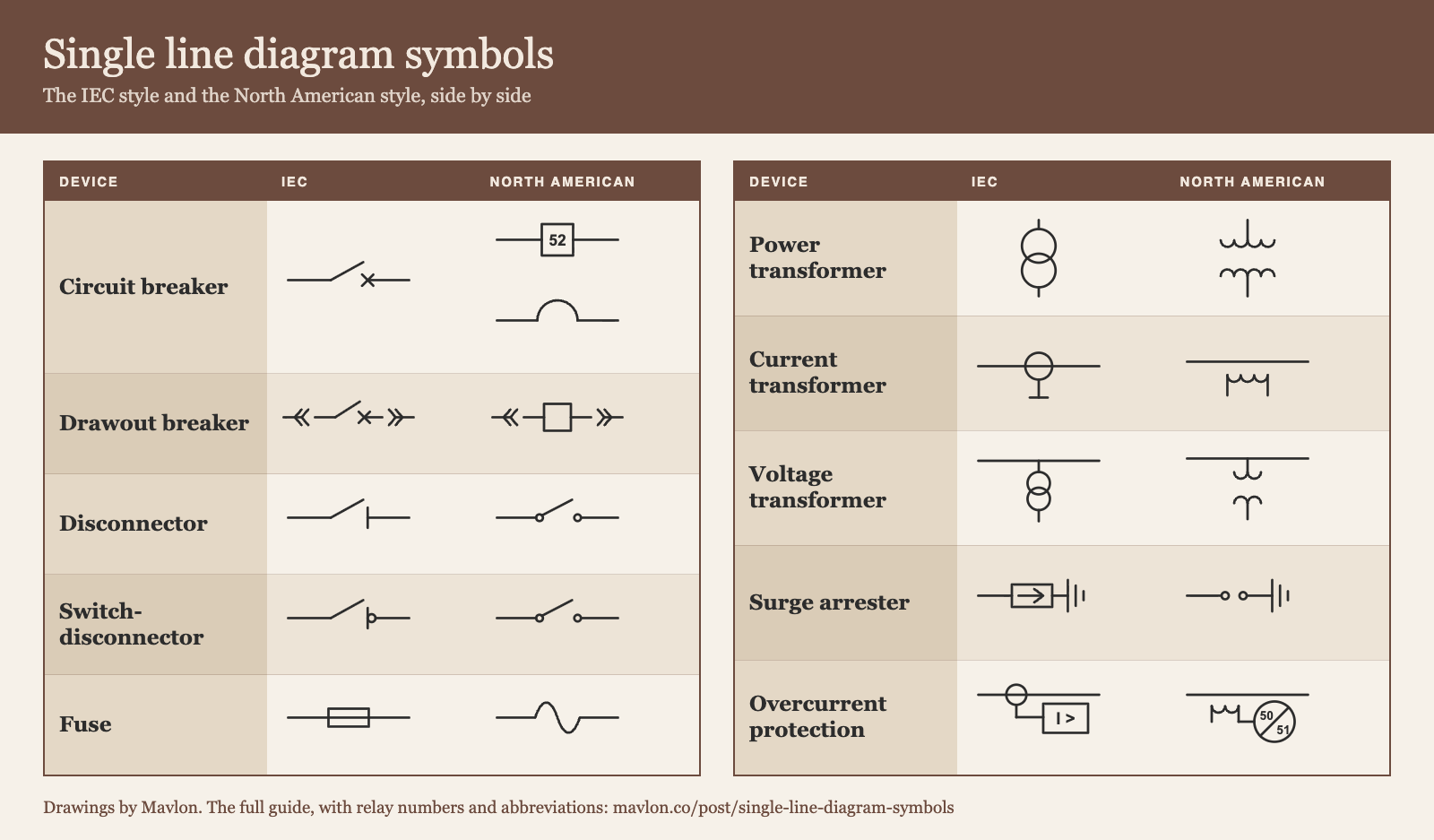
The two families of single line diagram symbols
A three-phase power system has three phase wires. A single line diagram draws one line to represent all three, and it puts one symbol on that line for each piece of equipment.
Even the name of the drawing changes with the country: engineers in the United States call it a one-line diagram, while most other countries call it a single line diagram.
The symbols come from two standards, and each standard grew up on a different continent.
IEC 60617, used in most of the world
IEC 60617 is the international standard for graphical symbols on electrical diagrams. Europe, India and most other countries outside North America draw to it, often through a national version such as DIN in Germany, NF in France or CEI in Italy.
The main idea behind it is simple. Every switching device starts from the same open contact, and a small mark on the fixed side tells you what kind of device it is. Once you know those marks, you can read a device you have never seen before.
IEEE 315 and ANSI Y32.2, used in North America
IEEE Std 315 is the American standard for the same job, and ANSI Y32.2 is the same document under its American national standard number. Drawings in the United States and Canada follow this standard.
This family relies on shapes and numbers. A breaker is a square or an arc, a transformer is two scalloped coils, and a relay is a circle with a number inside. The numbers come from IEEE C37.2, which gives every kind of device in a power system a number from 1 to 99.
"NOT ALL SYMBOLS APPLY, REFER TO FLOOR PLANS AND DRAWINGS"
Legend sheet E000 of a public Canadian switchgear tenderThat note sits under the legend of one of the drawings we read. It is a fair warning for any sheet: a legend is only a list of what the drafter might use, while the diagram itself shows what was actually used.
What we saw on ten public drawings
We read ten public single line diagrams by hand, going label by label. Two are from North America and eight are from other countries. The table below shows which family each drawing used and how its relays were marked.
| Where the drawing is from | What the sheet calls itself | Symbol family | How protection is marked |
|---|---|---|---|
| Ottawa, Canada: federal laboratory campus | Single line diagram | North American, with a legend on its own sheet | Device numbers in circles |
| San Antonio, United States: water utility | One-line diagram | North American | Device numbers in circles |
| Leipzig, Germany: tram substation | Übersichtsschaltplan | IEC | The relay's product type |
| Appenzell, Switzerland: village utility | Prinzipschema | IEC | The relay's product type |
| Marne, France: wind farm substation | Schéma unifilaire | IEC | A box named for the protection it gives |
| Terni, Italy: hospital substation | Schema generale | IEC | Device numbers for overcurrent |
| Lyngby, Denmark: university campus | A figure in the owner's standard | IEC | The relay's product type |
| Bogotá, Colombia: research building | Diagrama unifilar | IEC style | Fuse and breaker ratings only |
| Uttar Pradesh, India: low-voltage boards for a substation | Single line diagram | IEC style | Device numbers, with a legend on the sheet |
| Chhattisgarh, India: 400 kV switchyard | Single line diagram | IEC style | Device numbers on every bay |
Two things stand out in this table. First, the shapes follow the map, because every drawing from outside North America used IEC shapes. Second, the relay numbers do not follow the map. The Italian sheet and both Indian sheets used American device numbers on IEC drawings.
Because of this mix, you cannot learn one family and ignore the other. A European tender can give you a 51N relay, and a Canadian tender can give you a transformer drawn as two circles.
Switching devices: breaker, disconnector, switch and fuse
These are the symbols that matter most for the price, because each one stands for a different piece of equipment with a very different cost. The table below shows the same device drawn both ways.
| Device | IEC drawing | North American drawing | How to tell |
|---|---|---|---|
| Circuit breaker | IEC puts a small cross on the fixed contact. North America draws a square for a medium-voltage breaker, often marked 52, and an arc for a low-voltage breaker. | ||
| Drawout breaker | Both families put chevrons on each side of the device. The chevrons mean the breaker can be pulled out of its cell. | ||
| Disconnector | IEC puts a short bar across the fixed contact. North America draws a plain blade and may write 89 beside it. | ||
| Switch-disconnector, also called a load break switch | IEC adds a small circle to the bar. North America draws the same plain blade as before and says "load break" in the label. | ||
| Fuse | IEC draws a rectangle with the line running through it. North America draws an S-shaped curve, or a small rectangle between two terminals. | ||
| Switch and fuse together | Both draw the switch first and the fuse after it. The fuse rating is written beside the fuse. | ||
| Earthing switch | A blade to the ground symbol, often marked with 89 and a letter for ground | The far side of the blade goes to earth and not to another circuit. |
A cross, a bar or a circle changes the price
On an IEC sheet, a circuit breaker, a disconnector and a switch-disconnector all look like the same open contact. The only difference is the small mark on the fixed side, and that mark is only a few millimetres wide on a printed sheet.
- A cross means the device is a circuit breaker. It can interrupt a short circuit, and it needs a protection relay and current transformers to tell it when to open.
- A bar means the device is a disconnector. It makes a safe gap in a circuit that is already dead, and it must not be opened under load.
- A bar with a circle means the device is a switch-disconnector. It can open the normal load current, but it cannot clear a fault, so it usually comes with fuses.
A breaker panel costs far more than a switch panel. On a scanned drawing, the cross and the bar can blur into each other, which is why a careful reader checks the mark against the relay and the current transformers drawn beside it.
When the mark on a contact is unclear, look for a relay and current transformers on the same circuit. A breaker needs both of them. If the circuit has fuses and no relay, the device is almost always a switch-disconnector.
The square and the arc in North America
North American drawings show two kinds of breaker, and the shape tells you the voltage class before you even read a single label.
A square on the line is a medium-voltage breaker. Many drafters write 52 inside it or beside it, because 52 is the device number for an AC circuit breaker. An arc between two terminals is a low-voltage breaker, such as a molded case or an insulated case breaker.
The legend of the Canadian tender spells out how much the small details on the symbol mean:
"LOW VOLTAGE INSULATED CASE DRAW-OUT AIR CIRCUIT BREAKER, TRIP PLUG AND FRAME SIZE AS SHOWN"
Legend sheet E000, public Canadian switchgear tenderThat single line in the legend names four things you have to price: the type of breaker, the fact that it draws out, its frame size and its trip plug. The chevrons on the symbol are the only visual sign of the drawout construction.
Drawout or fixed
Chevrons on both sides of a breaker mean that it sits on a carriage and can be racked out of its cell. A breaker drawn without chevrons is fixed in place.
Drawout construction costs more because each cell needs a cradle, shutters and racking gear. Do not price drawout construction from the symbol alone. Drafters often copy the same breaker symbol across a whole lineup, so you should check the specification to see whether every breaker draws out or only the mains do.
Our guide to main-tie-main switchgear covers the other choices that a one-line diagram does not settle, such as who supplies the transfer scheme.
The contactor, in words
You will meet contactors in motor control centers more often than in switchgear. The IEC family marks a contactor with a small half circle on the contact. The North American family writes the letter C in a box, or draws two short parallel plates.
Transformers, current transformers and voltage transformers
Transformers are the easiest symbols to tell apart, because the two families use shapes that look nothing alike.
| Device | IEC drawing | North American drawing | How to tell |
|---|---|---|---|
| Power transformer, two windings | IEC draws two overlapping circles. North America draws two scalloped coils that face each other. | ||
| Current transformer | IEC draws a ring around the line. North America draws a small scalloped coil beside the line. | ||
| Voltage transformer | Both tap it off the line. IEC draws two small circles, and North America draws two small coils and calls it a potential transformer, or PT. |
What is written beside a power transformer
The symbol only tells you that a transformer is there. The price comes from the text written beside it, and that text follows its own habits in each family.
- Power. Both families give the power in kVA or MVA. A North American label such as 7500/9375 kVA gives two ratings, one for each cooling stage.
- Voltages. IEC sheets write 10/0.4 kV. North American sheets write 13.8 kV to 480Y/277 V, where the Y says the low-voltage winding is connected in star.
- Winding connection. IEC sheets write a vector group such as Dyn11 or Dyn5. The D is a delta winding on the high side, the y is a star winding on the low side, the n says the neutral is brought out, and the number gives the phase shift in steps of 30 degrees. North American sheets draw a small triangle and a small Y beside the coils.
- Impedance. IEC sheets write uk or Uz as a percentage, while North American sheets write %Z.
The impedance matters to a switchgear maker just as much as it does to the transformer maker. A lower impedance lets more fault current through, and that raises the short-circuit rating required for every board below the transformer.
How many current transformers, and of what class
One ring on an IEC line, or one small coil on a North American line, can stand for three current transformers, with one on each phase. Look for a small "3" or three short strokes beside the symbol.
The label beside the symbol gives the ratio and the accuracy class, and the two families write the class in different ways:
- A ratio such as 800/5 A or 800/1 A means that 800 amperes in the main circuit gives 5 amperes or 1 ampere to the relay. North America almost always uses 5 A, while IEC drawings use both.
- An IEC protection class looks like 5P20 or 5P10. The first number is the error in percent, P means protection, and the last number says how many times the rated current the transformer can carry before it stops being accurate.
- An IEC metering class looks like 0.5 or 0.2S. A smaller number is more accurate and costs more.
- A North American relaying class looks like C200 or C400, and a metering class looks like 0.3B0.5.
A circuit with separate cores for metering and for protection needs more current transformers than the symbol count suggests, so you need to read every label carefully.
Generators, motors, busbars and the parts around them
Several symbols are the same in both families. You can read these on any sheet without worrying about where the drawing came from.
| Device | IEC drawing | North American drawing | How to tell |
|---|---|---|---|
| Busbar | The same | A heavy line with the circuits tapped off it. The current rating is written along the bar. | |
| Generator | The same | A circle with the letter G. A wavy line inside means alternating current. | |
| Motor | The same | A circle with the letter M. | |
| Capacitor | The same | Two parallel plates. A bank of them corrects the power factor. | |
| Earth, or ground | The same | Three bars that get shorter. IEC calls it earth and North America calls it ground. | |
| Meter | The same | A circle with a letter: A for an ammeter and V for a voltmeter. Energy meters are usually a box marked kWh. | |
| Surge arrester | IEC draws a rectangle with an arrow inside, connected to earth. North America draws a gap connected to ground and often calls it a lightning arrester. |
The busbar carries three ratings, not one
The heavy line of a busbar usually has a current written along it, such as 2000 A. That number is the continuous rating. Two more numbers decide how the bar is built, and they are often written somewhere else on the sheet.
The first is the short-circuit rating, written in kA with a time, such as 50 kA for 1 s. The second is the voltage, along with the number of phases and wires. One of the Indian sheets we read writes all three ratings in a single line for each board, which is the clearest method we saw.
If you want to check a bar size against a current rating, our busbar calculator does the math for copper and aluminium.
Arrows, dashes and clouds
Three common marks are not symbols for equipment at all, but they still change the scope of a quote.
- A dashed outline or a dashed circuit usually means future or existing equipment. For example, the Canadian sheet draws its two future feeders with dashed lines.
- An arrow leaving the sheet means the circuit continues on another drawing. The equipment at the other end may or may not be in your scope.
- A cloud around part of the drawing marks a revision. Everything inside the cloud has changed since the last issue.
Protection: device numbers and IEC markings
Protection is where the two families differ the most, and it is also where a quote can quietly go wrong. A relay costs money, and so do the current transformers, the wiring and the testing that come with it.
| Function | IEC drawing | North American drawing | How to tell |
|---|---|---|---|
| Overcurrent protection | IEC writes the measured quantity in a box: the letter I with a greater-than sign. North America writes device numbers in a circle. |
The device numbers you will meet most
IEEE C37.2 gives each protection function a number. The table below lists the numbers that appear most often on switchgear drawings, along with the marking that an IEC drawing uses for the same function.
| Device number | What it does | IEC marking |
|---|---|---|
| 21 | Distance protection | Z< |
| 25 | Synchronism check before a breaker closes | Written out in words |
| 27 | Undervoltage | U< |
| 32 | Directional power, used against reverse power | P with an arrow |
| 46 | Phase unbalance in the current | I2> |
| 47 | Phase sequence of the voltage | Written out in words |
| 49 | Thermal overload of a machine or a transformer | The Greek letter theta with a greater-than sign |
| 50 | Instantaneous overcurrent | I>> |
| 51 | Time overcurrent | I> |
| 50N and 51N, or 50G and 51G | The same two functions for an earth fault | I0> or IE> |
| 52 | AC circuit breaker | The breaker symbol itself |
| 59 | Overvoltage | U> |
| 63 | Pressure switch, such as the gas relay of an oil transformer | Written out in words |
| 67 | Directional overcurrent | I> with an arrow |
| 79 | Automatic reclosing | Written out in words |
| 81 | Frequency, under or over | f< or f> |
| 86 | Lockout relay, which keeps a breaker open after a trip | Written out in words |
| 87 | Differential protection | Id> or a delta with I |
| 89 | Line switch, meaning a disconnector | The disconnector symbol itself |
The letters after the number
A letter after a device number narrows down its job. N means the relay is connected in the neutral, and G means ground. T means transformer and B means bus, so 87T is transformer differential protection and 87B is bus differential protection.
Two numbers joined by a slash, such as 50/51, mean that one relay does both jobs. That is the normal setup today, because a single multifunction relay can cover many device numbers.
Numbers from 95 to 99 are left open for special uses that the other numbers do not cover. One Indian drawing in our set defines 95 and 96 in its own legend, which is the right place to look for them.
One relay, many numbers
A modern protection relay is a single box that handles many functions. A drawing may list 50, 51, 50N, 51N and 86 on a feeder, and all of those functions can live inside one physical device.
Because of this, you should count relays by the boxes and the product types, not by the function numbers. Three of our ten drawings name the relay by its product type and give no function numbers at all. On those sheets, the written specification tells you which functions the relay must include.
Make a short list for each circuit: write down the device numbers or IEC markings on the drawing, the relay type if one is named, and the current transformer class. If the drawing asks for a function that the named relay does not have, write that down as a question for the customer before you price it.
Abbreviations printed beside the symbols
Most of the cost on a single line diagram hides in the short strings of letters and numbers printed beside each symbol. The same electrical rating often has one abbreviation in the IEC family and another in the North American family.
| What it means | IEC drawings | North American drawings |
|---|---|---|
| Rated current of a device | In, as in In = 1600 A | The frame and trip sizes, as in 1600AF/1200AT |
| The current the trip unit is set to | Ir, as in Ir = 0.95 x In | The long-time pickup, or the trip plug size |
| Fault current a breaker can interrupt | Icu and Ics, in kA | The interrupting rating, written kAIC |
| Fault current a bar or a breaker can carry for a short time | Icw, as in 50 kA for 1 s | The short-time rating, or the bus bracing |
| Fault current available at a point | Ik or Ik", from IEC 60909 | The available fault current, in kA sym |
| Rated voltage | Un or Ur | The voltage class, as in 15 kV class |
| Impulse voltage the insulation withstands | Uimp, or the lightning impulse level | BIL, as in 110 kV BIL |
| Trip functions of a breaker | L, S, I and G | LSIG, for long, short, instantaneous and ground |
| Number of poles | 3P, 4P or 3P+N | 3P or 4P, and 3 phase 4 wire for the system |
| Cable size | mm², as in 3x185 mm² | AWG or kcmil, as in 3 x 500 kcmil |
| Normal position of a contact or a breaker | NO and NC | N.O. and N.C. |
| Medium voltage and low voltage | MV and LV, or the local words | MV and LV |
Three abbreviations that cause the most trouble
Icu and Icw are not the same thing. Icu is the fault current a breaker can interrupt once. Icw is the fault current it can carry for a set time without opening, which matters when upstream breakers must wait for downstream breakers to trip first. A main breaker usually needs a high Icw, and that requires a more expensive breaker.
The frame size is not the trip size. On a North American label such as 1600AF/1200AT, the breaker frame is rated for 1600 A and the trip unit is set for 1200 A. You price a 1600 A frame, and the cable is sized for the 1200 A trip.
The local words for medium and low voltage change by country. German sheets write MS and NS, French sheets write HTA and BT, and Italian and Spanish sheets write MT and BT. They all mean the same two voltage levels.
For low-voltage boards, the standard behind the ratings changes the price as well. Our guide to UL 891 and UL 1558 explains where large owners draw the line between a switchboard and switchgear.
The same labels in six languages
A tender from another country gives you the same symbols with unfamiliar words beside them. The table below gives the standard term for each device in English, German, French, Spanish, Italian and Danish.
The German, French, Spanish and Italian terms are the ones printed in the International Electrotechnical Vocabulary, which the IEC publishes free of charge as Electropedia. We left out the gender marks and the extra words it prints in brackets.
Because that vocabulary does not include Danish, the Danish terms come from Danish regulations and the grid rules of Energinet, the Danish system operator.
| English | German | French | Spanish | Italian | Danish |
|---|---|---|---|---|---|
| Single line diagram | Einstrich-Netzschema | schéma unifilaire | esquema unifilar | schema unifilare | enstregsskema |
| Busbar | Sammelschiene | jeu de barres | juego de barras | sistema di sbarre | samleskinne |
| Circuit breaker | Leistungsschalter | disjoncteur | interruptor automático | interruttore | effektafbryder |
| Disconnector | Trennschalter | sectionneur | seccionador | sezionatore | adskiller |
| Switch-disconnector | Lasttrennschalter | interrupteur-sectionneur | interruptor-seccionador | interruttore di manovra-sezionatore | lastadskiller |
| Earthing switch | Erdungsschalter | sectionneur de terre | seccionador de puesta a tierra | sezionatore di terra | jordslutter |
| Fuse | Sicherung | fusible | fusible | fusibile | sikring |
| Contactor | Schütz | contacteur | contactor | contattore | kontaktor |
| Power transformer | Transformator | transformateur de puissance | transformador de potencia | trasformatore | transformer |
| Current transformer | Stromwandler | transformateur de courant | transformador de intensidad | trasformatore di corrente | strømtransformer |
| Voltage transformer | Spannungswandler | transformateur de tension | transformador de tensión | trasformatore di tensione | spændingstransformer |
| Surge arrester | Überspannungsableiter | parafoudre | pararrayos | scaricatore | overspændingsafleder |
| Rectifier | Gleichrichter | redresseur | rectificador | raddrizzatore | ensretter |
| Withdrawable part | Einschub | partie débrochable | parte desenchufable | parte estraibile | No source found |
| Short-circuit current | Kurzschlussstrom | courant de court-circuit | corriente de cortocircuito | corrente di cortocircuito | kortslutningsstrøm |
| Overcurrent protection | Überstromschutz | protection à maximum de courant | protección de sobreintensidad | protezione di massima corrente | overstrømsbeskyttelse |
| Low, medium and high voltage | Niederspannung, Mittelspannung, Hochspannung | basse tension, moyenne tension, haute tension | baja tensión, media tensión, alta tensión | bassa tensione, media tensione, alta tensione | lavspænding, mellemspænding, højspænding |
The words the drawings use instead
A working drawing does not always use the formal dictionary term. Here are the everyday words we met on the sheets themselves:
- German. The diagram was titled Übersichtsschaltplan on one sheet and Prinzipschema on another. An incoming feeder was called an Einspeisung, a panel was a Feld, and a transformer was shortened to Trafo.
- French. An incoming feeder was an Arrivée and an outgoing feeder was a Départ. Current transformers were marked TC, voltage transformers were marked TP, and the medium-voltage cable was called a câble HTA.
- Spanish. The diagram was called a diagrama unifilar. A panel of medium-voltage switchgear was a celda, and a low-voltage board was a tablero.
- Italian. The substation was a cabina, a switchboard was a quadro, and a spare circuit was marked riserva.
- Danish. A switchboard was a tavle, a bus coupler was a skinnekobler, and the substation was a transformerstation.
When a label is not in your dictionary, look at the symbol first. The symbol tells you the kind of device, and that narrows the foreign word down to two or three likely choices.
What the ten drawings taught us about reading them
We chose the ten drawings to be different from each other, so they are not a random sample of all tenders. Even so, they showed four practical problems that we did not expect when we started.
Seven of the ten had no text you could copy
Seven of the ten files had no text layer at all, and an eighth had a text layer for only part of the sheet. A PDF drawing with no text layer is just a flat picture. You cannot search it, and you cannot copy a rating out of it.
Some of those seven files were scans of paper drawings. Others were clean CAD drawings that had been saved as images, or had their letters turned into vector outlines. They look sharp to the eye, but every label still has to be read from the picture.
The legend is not always on the diagram
The bid packages showed three different ways a legend can arrive.
The Canadian package keeps its legend on a separate sheet, with two panels of symbols for the single line diagram. The Indian low-voltage drawing prints a legend for its relay numbers right on the sheet itself. The French sheet has a legend too, but it only covers the key interlocks.
When a package does include a legend, you should read it before you read the diagram. It tells you which symbol family the drafter used and which local habits they added on top. When a package has no legend, you have to know the symbols already, or ask the engineer.
Small text decides the price
The symbols are the large shapes on the sheet, while the ratings are in the small text. On one Italian drawing, the ratings could only be read clearly at 200 dots per inch or higher. On a Danish drawing, which was a low-resolution image pasted into a document, the smallest labels could barely be read at all.
If you receive a blurry drawing like that, ask for the original file before you price from it. A guess at a blurred rating is a guess at the price.
The sheet does not always agree with itself
On the Canadian tender, the drawing shows eleven cells, while the written overview of the work asks for ten. On the German tender, one panel is drawn at 630 A, while the bill of quantities lists it as a 200 A switch.
Neither mistake is unusual. A single line diagram is drawn by hand in a CAD program, and it gets revised many times before it reaches a bidder. You should treat any conflict between documents as a question for the engineer, and state clearly in your quote which reading you priced.
What a symbol does not tell you
A symbol tells you what kind of device sits on the line. To build a quote, you need six more pieces of information, and none of them is in the shape itself.
- The rating. This is written in the label beside the symbol, or in a schedule on another sheet.
- The construction. Whether the gear is fixed or drawout, whether it is air or gas insulated, and the form of internal separation inside the board are usually written in the specification.
- The make. Some sheets name a specific product type, and the specification says whether an equal product is allowed.
- The quantity per phase. A single symbol on the line can stand for three devices, one for each phase.
- Who supplies it. The utility's metering, the protection relays and the power cables often belong to someone else's scope.
- Whether it exists yet. Dashed lines and the words future, existing and spare all change what you actually need to supply.
Before you price from a single line diagram, write down eight things for each circuit: the device, its rating, whether it is fixed or drawout, the relay functions, the current transformer ratio and class, the cable, who supplies it, and whether it is new, existing or future.
Any item you cannot fill in becomes a question to send to the customer.
Our guide on how to quote switchgear shows where each of those answers usually sits in a specification.
A one-page copy of the symbols
We put the symbol tables from this guide, the device numbers and the abbreviations onto a short PDF that you can print and keep beside a drawing. It has no sign-up form.
Open the PDF of single line diagram symbols, IEC and North American side by side.
How long this takes by hand, and what we built for it
A dense single line diagram takes most of a working day to read by hand. Most of that time goes into reading small text: finding each rating, matching it to its symbol, and checking it against the written list of equipment.
That careful reading is the first step of every switchgear quote, and it is the exact step our product handles. Mavlon's AI Quoting Engine reads the bid package a customer sends you, including the single line diagram, the specification and the bill of quantities, and turns it into a priced draft quote in your own pricing.
It reads one-line diagrams drawn the North American way and single line diagrams drawn the IEC way, and it also reads sheets that are flat scans with no text layer. We do not claim a single accuracy number for every drawing, because scan quality, symbol styles and languages all affect the result.
Every line of the draft quote points back to the exact place on the drawing or the page it came from. Where two documents disagree, the engine shows you both readings so that you can choose the right one.
This is not catalogue pricing. It prices custom equipment from the customer's documents, using your rates and your past quotes, and your estimator checks the draft and sets the final number. You can see it working through two public switchgear drawings on our page about AI to read electrical drawings.
Sources
Here are the standards behind the two symbol families:
- IEC 60617, Graphical symbols for diagrams, the official database of IEC symbols.
- IEEE Std 315-1975, Graphic Symbols for Electrical and Electronics Diagrams, which is also published as ANSI Y32.2.
- IEEE Std C37.2, Standard Electrical Power System Device Function Numbers, Acronyms, and Contact Designations.
- IEC Electropedia, the International Electrotechnical Vocabulary, which we used for the terms in each language.
Here are the ten public drawings we read, all published by their owners:
- Public Works and Government Services Canada, KC01 Complex switchgear upgrade, Ottawa, solicitation EP067-162617, drawings E000 and E201 (2016).
- San Antonio Water System, IFB 18-18099, early procurement of medium voltage switchgear, sheet E-1007 (2018).
- Leipziger Verkehrsbetriebe, tender 2026-RL-27-02, lot VE 02, sheet 01_03_01, Übersichtsschaltplan.
- Elektra Oberegg, Trafostation Haggen, Prinzipschema, plan 212956/5.1 (2017), published in a public consultation of the Canton of Appenzell Innerrhoden.
- Parc éolien de Fère-Champenoise, delivery substation PDL 1, Plan 26 (2020), published in a public inquiry of the Préfecture de la Marne.
- Azienda Ospedaliera Santa Maria di Terni, Delibera DG 375/2024, drawing 22-420-E02.
- Technical University of Denmark, 450 El, Bilag 01, Information om DTUs El-infrastruktur, version 1.1 (2018).
- Servicio Geológico Colombiano, Centro de Excelencia en Geociencias, Bogotá, sheet U-B1-1, Diagrama unifilar general (2018).
- BHEL Transmission Projects Division, specification TB-404-316-026, LT switchgear for the Rasra substation.
- BHEL Transmission Projects Division, specification TB-408-510-010, extension of the 400 kV Champa substation.
The symbol drawings on this page are our own. Have you found a mistake? Write to atishay@mavlon.co and we will fix it.
Talk to us about your drawings
If your team quotes switchgear, switchboards or power equipment from single line diagrams, bring one package. We will read it with you and show every board, every rating and every place where the documents disagree, tied to its sheet.
Or see how Mavlon reads single line diagrams, on one page: AI to read electrical drawings.
Book a demo